Making a Mask with an E-Ink Banner

We wear masks out in public so often it occurred to me we should be able to dynamically customize them to suit our moods and maybe even sell advertising space! Masks also hide a good part of our facial expressions and so I wondered if I couldn't create a portion of a mask that lets people know how we're doing underneath. So I prototyped a wearable mask with a flexible e-ink display that can dynamically show content.
Getting the Parts
Adafruit is my go-to place for electronics prototyping, especially when it comes to Arduino tinkering. After some research, it looked like the Feather + E-ink Featherwing would be the right base for this project. I especially wanted something lightweight that could work on the go (ie. have a battery-powered option and talk to my phone). Since I knew I wanted to wrap the display on my mask, the display needed to be flexible and big enough to read from at least 6 feet away.
Here's the parts list I settled on:
- 1 x 2.9” Flexible Monochrome eInk / ePaper Display (296x128 Monochrome) [ID:4262] = $26.95
- 1 x 24-pin eInk / ePaper Extension Cable 0.5mm Pitch - 25cm Long [ID:4230] = $1.35
- 1 x Adafruit eInk Feather Friend with 32KB SRAM[ID:4446] = $8.95
- 1 x Header Kit for Feather - 12-pin and 16-pin Female Header Set [ID:2886] = $0.95
- 1 x Lithium Ion Polymer Battery - 3.7v 150mAh [ID:1317] = $5.95
- 1 x Short Headers Kit for Feather - 12-pin + 16-pin Female Headers [ID:2940] = $1.50
- 1 x Adafruit Feather M0 Bluefruit LE [ID:2995] = $29.95
- 1 x 24-pin FFC / FPC Extender [ID:4524] = $0.86
Electronics Assembly and Setup

Soldiering the header kit to the feather and featherwing was straightforward, after I dug up an old breadboard to keep the pins in place. The li ion battery attaches to the feather and is charged (slowly) when the micro-USB power supply/data cable is connected. A very nice feature of the feather design is the ability to jump over to battery power once the micro-USB is disconnected.
The next step was to download the latest Arduino IDE and install the Bluetooth and Eink libraries. The board can be interacted with via bluetooth and a mobile app called BlueFruit Connect.
Combining demo scripts for the Bluetooth interaction and E-ink display, I hacked together a little Arduino code which allows the user to type in messages to the their phone and have it show up on the display.
| /********************************************************************* | |
| maskdisplay.ino | |
| Arduino code adapted from adafruit examples to display text to e-ink via bluetooth. | |
| - Josh Bloom (2020) | |
| This is an example for our nRF51822 based Bluefruit LE modules | |
| Pick one up today in the adafruit shop! | |
| Adafruit invests time and resources providing this open source code, | |
| please support Adafruit and open-source hardware by purchasing | |
| products from Adafruit! | |
| MIT license, check LICENSE for more information | |
| All text above, and the splash screen below must be included in | |
| any redistribution | |
| *********************************************************************/ | |
| #include <Arduino.h> | |
| #include <SPI.h> | |
| #include <Adafruit_GFX.h> // Core graphics library | |
| #include "Adafruit_EPD.h" | |
| #include "Adafruit_BLE.h" | |
| #include "Adafruit_BluefruitLE_SPI.h" | |
| #include "Adafruit_BluefruitLE_UART.h" | |
| #include "BluefruitConfig.h" | |
| #define EPD_CS 9 | |
| #define EPD_DC 10 | |
| #define SRAM_CS 6 | |
| #define EPD_RESET 5 // can set to -1 and share with microcontroller Reset! | |
| #define EPD_BUSY -1 // can set to -1 to not use a pin (will wait a fixed delay) | |
| #if SOFTWARE_SERIAL_AVAILABLE | |
| #include <SoftwareSerial.h> | |
| #endif | |
| /* Uncomment the following line if you are using 2.9" EPD */ | |
| Adafruit_IL0373 display(296, 128, EPD_DC, EPD_RESET, EPD_CS, SRAM_CS, EPD_BUSY); | |
| #define FLEXIBLE_290 | |
| /*========================================================================= | |
| APPLICATION SETTINGS | |
| FACTORYRESET_ENABLE Perform a factory reset when running this sketch | |
| Enabling this will put your Bluefruit LE module | |
| in a 'known good' state and clear any config | |
| data set in previous sketches or projects, so | |
| running this at least once is a good idea. | |
| When deploying your project, however, you will | |
| want to disable factory reset by setting this | |
| value to 0. If you are making changes to your | |
| Bluefruit LE device via AT commands, and those | |
| changes aren't persisting across resets, this | |
| is the reason why. Factory reset will erase | |
| the non-volatile memory where config data is | |
| stored, setting it back to factory default | |
| values. | |
| Some sketches that require you to bond to a | |
| central device (HID mouse, keyboard, etc.) | |
| won't work at all with this feature enabled | |
| since the factory reset will clear all of the | |
| bonding data stored on the chip, meaning the | |
| central device won't be able to reconnect. | |
| MINIMUM_FIRMWARE_VERSION Minimum firmware version to have some new features | |
| MODE_LED_BEHAVIOUR LED activity, valid options are | |
| "DISABLE" or "MODE" or "BLEUART" or | |
| "HWUART" or "SPI" or "MANUAL" | |
| -----------------------------------------------------------------------*/ | |
| #define FACTORYRESET_ENABLE 1 | |
| #define MINIMUM_FIRMWARE_VERSION "0.6.6" | |
| #define MODE_LED_BEHAVIOUR "MODE" | |
| /*=========================================================================*/ | |
| // Create the bluefruit object, either software serial...uncomment these lines | |
| /* | |
| SoftwareSerial bluefruitSS = SoftwareSerial(BLUEFRUIT_SWUART_TXD_PIN, BLUEFRUIT_SWUART_RXD_PIN); | |
| Adafruit_BluefruitLE_UART ble(bluefruitSS, BLUEFRUIT_UART_MODE_PIN, | |
| BLUEFRUIT_UART_CTS_PIN, BLUEFRUIT_UART_RTS_PIN); | |
| */ | |
| /* ...or hardware serial, which does not need the RTS/CTS pins. Uncomment this line */ | |
| // Adafruit_BluefruitLE_UART ble(Serial1, BLUEFRUIT_UART_MODE_PIN); | |
| /* ...hardware SPI, using SCK/MOSI/MISO hardware SPI pins and then user selected CS/IRQ/RST */ | |
| Adafruit_BluefruitLE_SPI ble(BLUEFRUIT_SPI_CS, BLUEFRUIT_SPI_IRQ, BLUEFRUIT_SPI_RST); | |
| /* ...software SPI, using SCK/MOSI/MISO user-defined SPI pins and then user selected CS/IRQ/RST */ | |
| //Adafruit_BluefruitLE_SPI ble(BLUEFRUIT_SPI_SCK, BLUEFRUIT_SPI_MISO, | |
| // BLUEFRUIT_SPI_MOSI, BLUEFRUIT_SPI_CS, | |
| // BLUEFRUIT_SPI_IRQ, BLUEFRUIT_SPI_RST); | |
| // A small helper | |
| void error(const __FlashStringHelper*err) { | |
| Serial.println(err); | |
| while (1); | |
| } | |
| /**************************************************************************/ | |
| /*! | |
| @brief Sets up the HW an the BLE module (this function is called | |
| automatically on startup) | |
| */ | |
| /**************************************************************************/ | |
| void setup(void) | |
| { | |
| while (!Serial); // required for Flora & Micro | |
| delay(500); | |
| Serial.begin(115200); | |
| Serial.println(F("Adafruit Bluefruit Command Mode Example")); | |
| Serial.println(F("---------------------------------------")); | |
| display.begin(); | |
| #if defined(FLEXIBLE_213) || defined(FLEXIBLE_290) | |
| // The flexible displays have different buffers and invert settings! | |
| display.setBlackBuffer(1, false); | |
| display.setColorBuffer(1, false); | |
| #endif | |
| display.clearBuffer(); | |
| display.setTextWrap(true); | |
| display.setCursor(5, 5); | |
| display.fillScreen(EPD_WHITE); | |
| display.setTextColor(EPD_BLACK); | |
| display.setTextSize(2); | |
| display.println("Please connect \n MaskDisplay using \n Bluetooth and the \n Bluefruit Connect App \n on your phone."); | |
| display.display(); | |
| /* Initialise the module */ | |
| Serial.print(F("Initializing the Bluefruit LE module: ")); | |
| if ( !ble.begin(VERBOSE_MODE) ) | |
| { | |
| error(F("Couldn't find Bluefruit, make sure it's in CoMmanD mode & check wiring?")); | |
| } | |
| Serial.println( F("OK!") ); | |
| if ( FACTORYRESET_ENABLE ) | |
| { | |
| /* Perform a factory reset to make sure everything is in a known state */ | |
| Serial.println(F("Performing a factory reset: ")); | |
| if ( ! ble.factoryReset() ){ | |
| error(F("Couldn't factory reset")); | |
| } | |
| } | |
| /* Disable command echo from Bluefruit */ | |
| ble.echo(false); | |
| Serial.println("Requesting Bluefruit info:"); | |
| /* Print Bluefruit information */ | |
| ble.info(); | |
| Serial.println(F("Please use Adafruit Bluefruit LE app to connect in UART mode")); | |
| Serial.println(F("Then Enter characters to send to Bluefruit")); | |
| Serial.println(); | |
| ble.verbose(false); // debug info is a little annoying after this point! | |
| /* Wait for connection */ | |
| while (! ble.isConnected()) { | |
| delay(500); | |
| } | |
| // LED Activity command is only supported from 0.6.6 | |
| if ( ble.isVersionAtLeast(MINIMUM_FIRMWARE_VERSION) ) | |
| { | |
| // Change Mode LED Activity | |
| Serial.println(F("******************************")); | |
| Serial.println(F("Change LED activity to " MODE_LED_BEHAVIOUR)); | |
| ble.sendCommandCheckOK("AT+HWModeLED=" MODE_LED_BEHAVIOUR); | |
| Serial.println(F("******************************")); | |
| } | |
| Serial.println("Delaying 10 sec"); | |
| delay(10000); | |
| Serial.println("Finished delay 10 sec"); | |
| } | |
| /**************************************************************************/ | |
| /*! | |
| @brief Constantly poll for new command or response data | |
| */ | |
| /**************************************************************************/ | |
| void loop(void) | |
| { | |
| // Check for user input | |
| char inputs[BUFSIZE+1]; | |
| char output[BUFSIZE+1]; | |
| if ( getUserInput(inputs, BUFSIZE) ) | |
| { | |
| // Send characters to Bluefruit | |
| Serial.print("[Send] "); | |
| Serial.println(inputs); | |
| ble.print("AT+BLEUARTTX="); | |
| ble.println(inputs); | |
| // check response stastus | |
| if (! ble.waitForOK() ) { | |
| Serial.println(F("Failed to send?")); | |
| } | |
| } | |
| // Check for incoming characters from Bluefruit | |
| ble.println("AT+BLEUARTRX"); | |
| ble.readline(); | |
| if (strcmp(ble.buffer, "OK") == 0) { | |
| // no data | |
| return; | |
| } | |
| // Some data was found, its in the buffer | |
| Serial.print(F("[Recv] ")); | |
| String thisString = ble.buffer; | |
| Serial.println(thisString); | |
| display.clearBuffer(); | |
| display.setCursor(5, display.height()/4); | |
| display.fillScreen(EPD_WHITE); | |
| display.setTextColor(EPD_BLACK); | |
| if (thisString.length() < 16) { | |
| display.setTextSize(4); | |
| } else { | |
| display.setTextSize(2); | |
| } | |
| display.println(thisString); | |
| display.display(); | |
| // Serial.println(ble.buffer); | |
| Serial.println("Delaying 10 sec"); | |
| delay(10000); | |
| Serial.println("Finished delay 10 sec"); | |
| ble.waitForOK(); | |
| } | |
| /**************************************************************************/ | |
| /*! | |
| @brief Checks for user input (via the Serial Monitor) | |
| */ | |
| /**************************************************************************/ | |
| bool getUserInput(char buffer[], uint8_t maxSize) | |
| { | |
| // timeout in 100 milliseconds | |
| TimeoutTimer timeout(100); | |
| memset(buffer, 0, maxSize); | |
| while( (!Serial.available()) && !timeout.expired() ) { delay(1); } | |
| if ( timeout.expired() ) return false; | |
| delay(2); | |
| uint8_t count=0; | |
| do | |
| { | |
| count += Serial.readBytes(buffer+count, maxSize); | |
| delay(2); | |
| } while( (count < maxSize) && (Serial.available()) ); | |
| return true; | |
| } |
To protect the display, I made sure that the e-ink display cannot be changed more than once per 10 seconds.
Sewing it in
I found a cloth mask with a few cotton layers that I could use to cut out a window the display, with the connector pins sticking out of the side. Placing the display inside the window, I then sewed (crudely) around the display being careful not to pierce it.
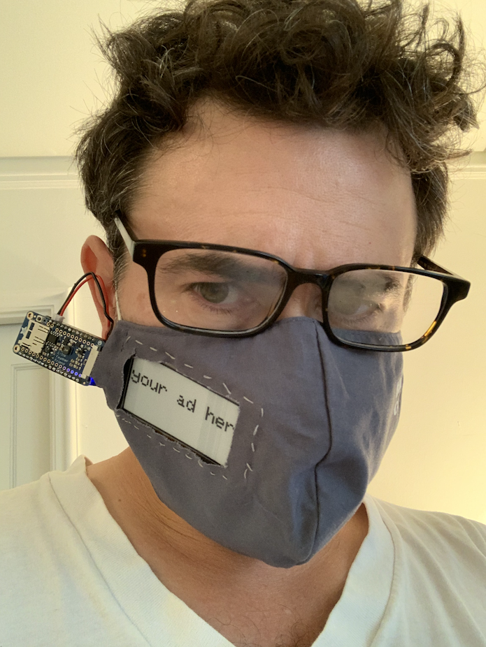
The Result
The prototype turned out pretty much as I had hoped (apologizes for the unkempt hair).

You can see a little demo here:
Next Steps
I initially forgot to order the PIN extender for the ribbon cable, which means I currently have to place the electronics directly next to the mask, instead of around the back of the head (say under a hat). Also, I didn't yet manage to get images working (since that required an SD card). Perhaps the destiny is that we can sell our GPS location (and beacon IDs of people nearby) to companies and have them dynamically upload advertisements as we go about our business. Yeah, maybe that's too dystopic of an idea even for 2020!